I want to drive Rainbowduino v3 boards from my PixelController software. PixelController sends data via ethernet to the Raspberry Pi, the Raspberry Pi then sends out the recieved data via I2C bus. Make sure read my blog post how to setup I2C on the RPI (and connect both devices).
So I wrote a Netty based Java application using Pi4J which does exactly this. The UDP2I2C source is published on GitHub: https://github.com/neophob/udp-to-i2c.
My application receive UDP data in the TPM2.net (german forum) format, converts the 24bpp data to 12bpp and sends out the data on the I2C bus to a Rainbowduino v3. However it’s quite easy to adapt the software to do other things.
Here’s a primitive schema how everything is conected:
1 | [PixelController]--<UDP>--[Raspberry PI]--<I2C>--[Rainbowduino v3]--<I2C>--[Rainbowduino v3]... |

A note about the performance, I send about 130 UDP packets per second, contains 192 bytes from my PixelController software to the RPI. The RPI needs less than 10% CPU and less than 5% RAM using Java “build 1.8.0-ea-b36e”.
Detailed installation instructions
Setup Rainbowduinos
Function: display content on the LED matrix
Needed arduino library: timer1
Make sure you patched the I2C speed of the arduino to 400khz, see this blog post, chapter “Increase the I2C speed on the Arduino“. If you omit this step, the communitcation will not work!
Firmware for the Rainbowduinos:
Download udp2i2c-1.0.zip from https://code.google.com/p/neorainbowduino/downloads/list and open the firmware at Arduino/rv3_tmp/rv3_tmp.ino (or see the code here). You need to adjust this definition:
1 | #define I2C_ADDRESS 6 |
This is the unique I2C address for a Rainbowduino, make sure you assign each address only once and write down the I2C address! For example start by number 4 and increase the number for the next Rainbowduino.
Setup Raspberry PI
Function: convert network data to I2C.
Make sure you installed JDK8 Hard Float on your RPI. Here is a setup guide from Oracle.
Download udp2i2c to you Raspberry Pi.
To enable udp2i2c after a reboot, copy the usp2i2c from the init.d into the init.d dir and enable daemon:
1 2 | pi@raspberrypi ~/udp2i2c/init.d $ sudo cp ./udp2i2c /etc/init.d/ pi@raspberrypi ~/udp2i2c/init.d $ sudo update-rc.d udp2i2c enable |
The configuration for udp2i2c is stored in the file /etc/init.d/udp2ic2:
1 | args="-p 65506 -b 1 -t 4 -d 5" |
This means udp2ic2 listen on port 65506, use I2C bus 1, use I2C target 4 (the Rainbowduino) and delay 5ms after a I2C packed is sent out. The important parts of the parameter are -b (select I2C bus number) and -t (selects I2C target address)
If you use a Raspberry Pi rev1 (256mb ram) you need to select “-b 0″, if you use a rev2 Raspberry Pi you need to select “-b 1″. The -t argument define the target Rainbowduino parameters you defined while you flashed the Rainbowduinos. For example if you flashed 5 Rainbowduinos use “-t 4:5:6:7:8″.
Example for 5 Rainbowduinos on a Raspberry Pi rev1:
1 | args="-p 65506 -b 0 -t 4:5:6:7:8 -d 5" |
Example for 5 Rainbowduinos on a Raspberry Pi rev2:
1 | args="-p 65506 -b 1 -t 4:5:6:7:8 -d 5" |
Use i2cdetect to see if your Rainbowduinos are available on the I2C bus.
I used a WLAN adapter on my Raspberry PI, see http://neophob.com/2013/04/another-raspberry-pi-wlan-installation/ for more details.
Setup your Computer
Function: Generate animation using PixelController.
Install pixelcontroller v1.3.2-beta2 (or later) and use the config file from the udp2i2c package “PixelController/config.properties“. Copy this file and overwrite the existing config.properties file in the data subdirectory of PixelController.
Define how much Rainbowduinos you’re using, find this line:
1 | tpm2net.layout.row1=NO_ROTATE,NO_ROTATE,NO_ROTATE,NO_ROTATE,NO_ROTATE |
This means we defined 5 output devices, each NO_ROTATE define an output device.
You also need to define the IP address of the Raspberry Pi in the config file:
1 | tpm2net.ip=192.168.111.20 |
That’s it, fire up PixelController and have fun!
Here is a video of the whole installation in action (by Ryan Longo):
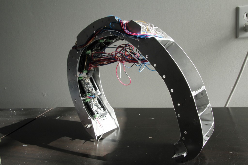
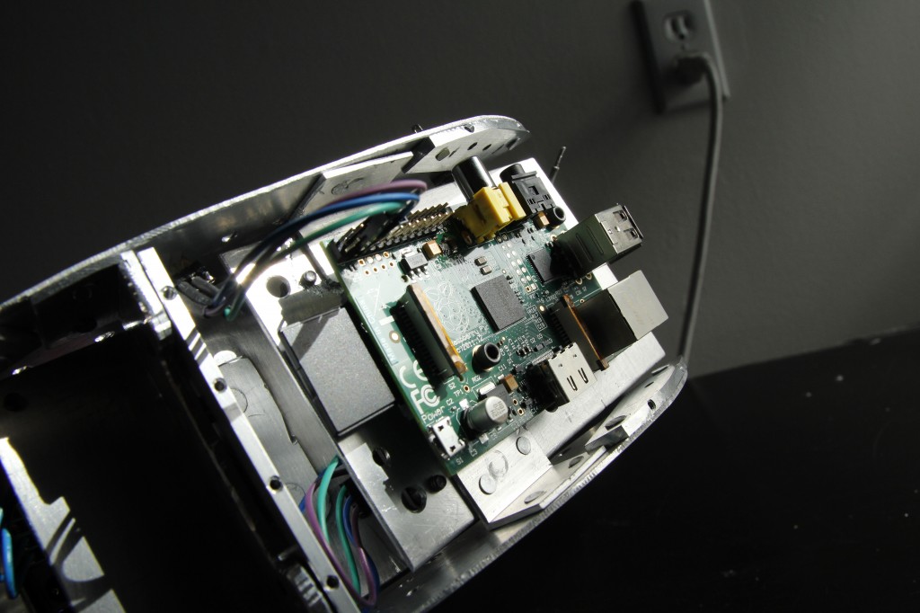
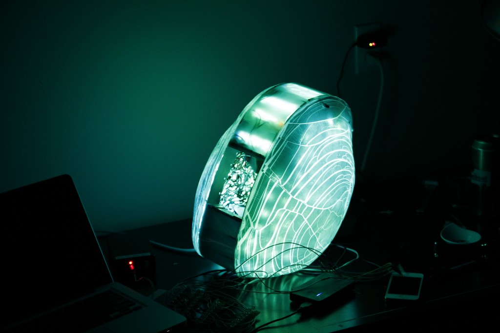
More images of the final product:

And this is a video of the final product, testing the wireless range:
Credits
Idea/Hardware assembly: Ryan Longo
Software: Michael Vogt
Thanks again Ryan Longo for the interesting project!