In a previous blog post I wrote about my issues with a LPD6803 based installation and long cables. To illustrate my installation I paste the wiring diagram here:
Clik here to view.
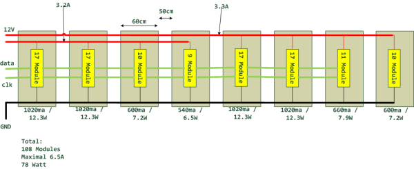
After some exhausting debug sessions I found several issues.
1) Check your installation
… especially after some late night hacking sessions. For example this cable
Clik here to view.
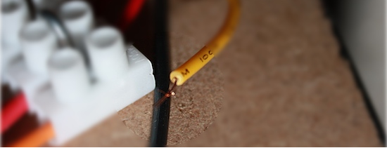
should carry more than 3 Ampere@12 Volt, BAD idea!
2) Check for common Ground
Ground is the reference point for the data lines. With different cable lengths to the power supply you can have major potential differences, this is kinda bad. In this example the ground cable is NOT routed:
Clik here to view.

Good Cabling, the ground cable is routed:
Clik here to view.

3) Use a dead simple circuit simulator
Check http://www.falstad.com/circuit/ for a simple and easy to use circuit simulator, thanks for this Java application! Great to debug your hardware circuits.
Clik here to view.
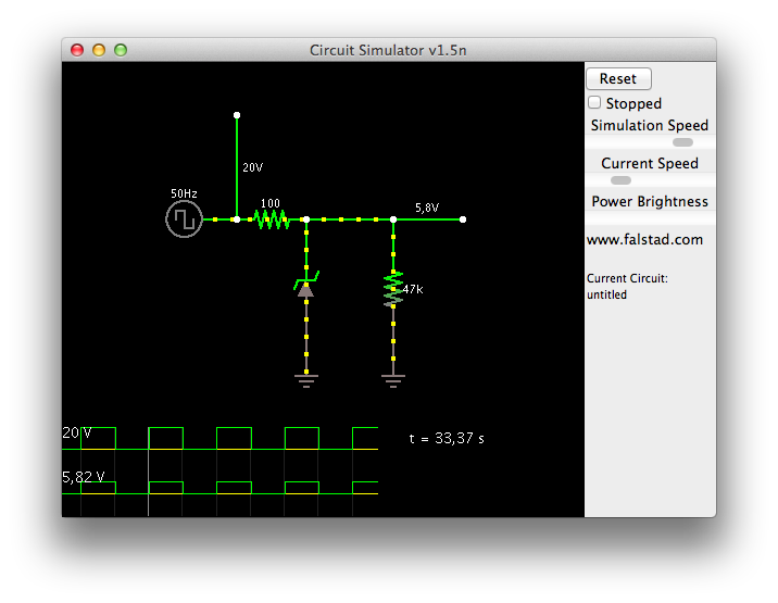
4) SPI Buffer (74AC245N) to improve the SPI Clock Signal
The only problem left were the two last modules, they just flicker from time to time. Thanks to Andre Zibell from the http://www.ledstyles.de board, he designed a busdriver to clean a (SPI) signal with a 74AC245N IC (Cornerpinning busdriver):
Clik here to view.
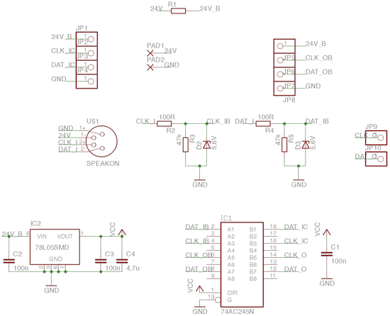
Andre was kind enough to send me two PCB’s, unfortunately I don’t really like (can?) solder SMT components, thats why I had to use a breadboard. I found BlackBoard breadboard designer very useful:
Clik here to view.
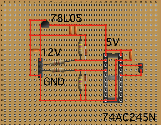
I build my first prototype on breadboard:
Image may be NSFW.
Clik here to view.
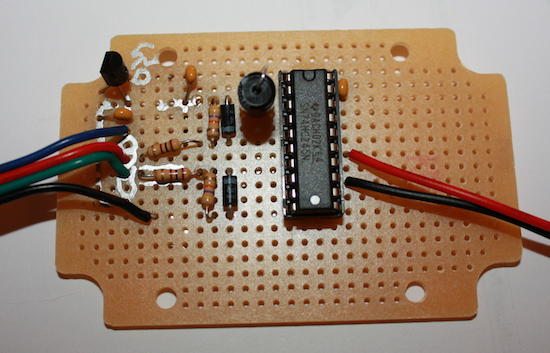
Image may be NSFW.
Clik here to view.
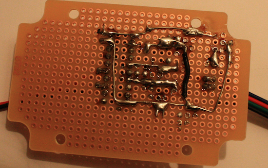
I installed the buffer breadboard after 4 large modules, the result was disastrous! No LED was blinking correctly after the breadboard, so I hooked up my DSO Quad and took a look at the signals:
Clik here to view.
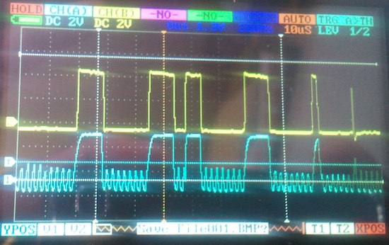
The cyan signal shows the input signal to the breadboard while the yellow output shows the output. Conclusion:
- The buffer breadboard is working, the signal flanks are steeper
- The signal is already greatly distorted, I need an earlier buffer breadboard. The signal flanks are too weak to form a clean “up” signal, so they get crippled
I use an 1 kOhm resistor between Clock and Ground, this improved the clock signal.
5) SPI Speed
The faster the SPI signal is, the more vulnerable it is. Take a look at this chart:
1 2 3 | SPI_CLOCK_DIV64 - 0.25MHz - 4uS per wave length SPI_CLOCK_DIV32 - 0.50MHz - 2uS per wave length SPI_CLOCK_DIV16 - 1.00 MHz - 1uS per wave length |
If your hardware (cable length…) is not optimal, reduce the SPI speed. This sounds very easy in theory, but its more difficult in practice, especially if you have an ISR to shift out some data, take a look at this real life example:
1 2 | strip.setCPUmax(80); // Setup TimerOne ISR to shift out data strip.begin(SPI_CLOCK_DIV32); // Start up the LED counter 0.5MHz |
The code above was working fine, but the last modules were not working fine. I reduced the SPI clock speed to 0.25MHz but the update speed was extremely slow. I did some experimenting and found out that I had to lower the CPU usage:
1 2 | strip.setCPUmax(49); // Setup TimerOne ISR to shift out data strip.begin(SPI_CLOCK_DIV64); // Start up the LED counter 0.25MHz |
This was finally the solution (don’t forget the 1kOhm resistor between CLK and DATA!), without additional hardware (speak: no SPI buffer)!. After countless hours, the installation finally works!
Other notable remarks:
- Never EVER prepare cables on your own!
- Create a project log, so you need to search each bug only once…
Thanks to LED Styles and Dangerous Prototype for your help!
Update 29.5:
Thanks to Bertho from the Dangerous Prototype forum, he wrote a very detailed Blog entry “Cable Connected, Signal Lost”, a great post!